

20
2026
-
10
From UAV Platforms to Intelligent Equipment: How Mechanical and Electronic Systems Work Together
An industrial UAV is an intelligent electromechanical system. This article explains how structure, actuation, sensing, electronic control, power, communication, manufacturing, and service work together to create reliable intelligent equipment.


Author:
From UAV Platforms to Intelligent Equipment: How Mechanical and Electronic Systems Work Together
Primary keyword: intelligent electromechanical equipment
Secondary keywords: industrial UAV system, UAV mechanical and electronic system, intelligent equipment manufacturer, integrated UAV solutions, servo and actuator systems
An industrial UAV is not an isolated aircraft. It is an intelligent electromechanical system in which structure, propulsion, actuation, sensing, electronic control, power, communication, payloads, and ground equipment must work together. A reliable platform depends not only on whether it can fly, but also on whether every mechanical movement can be commanded, every important state can be measured, and every subsystem can continue operating within a clearly defined mission envelope.
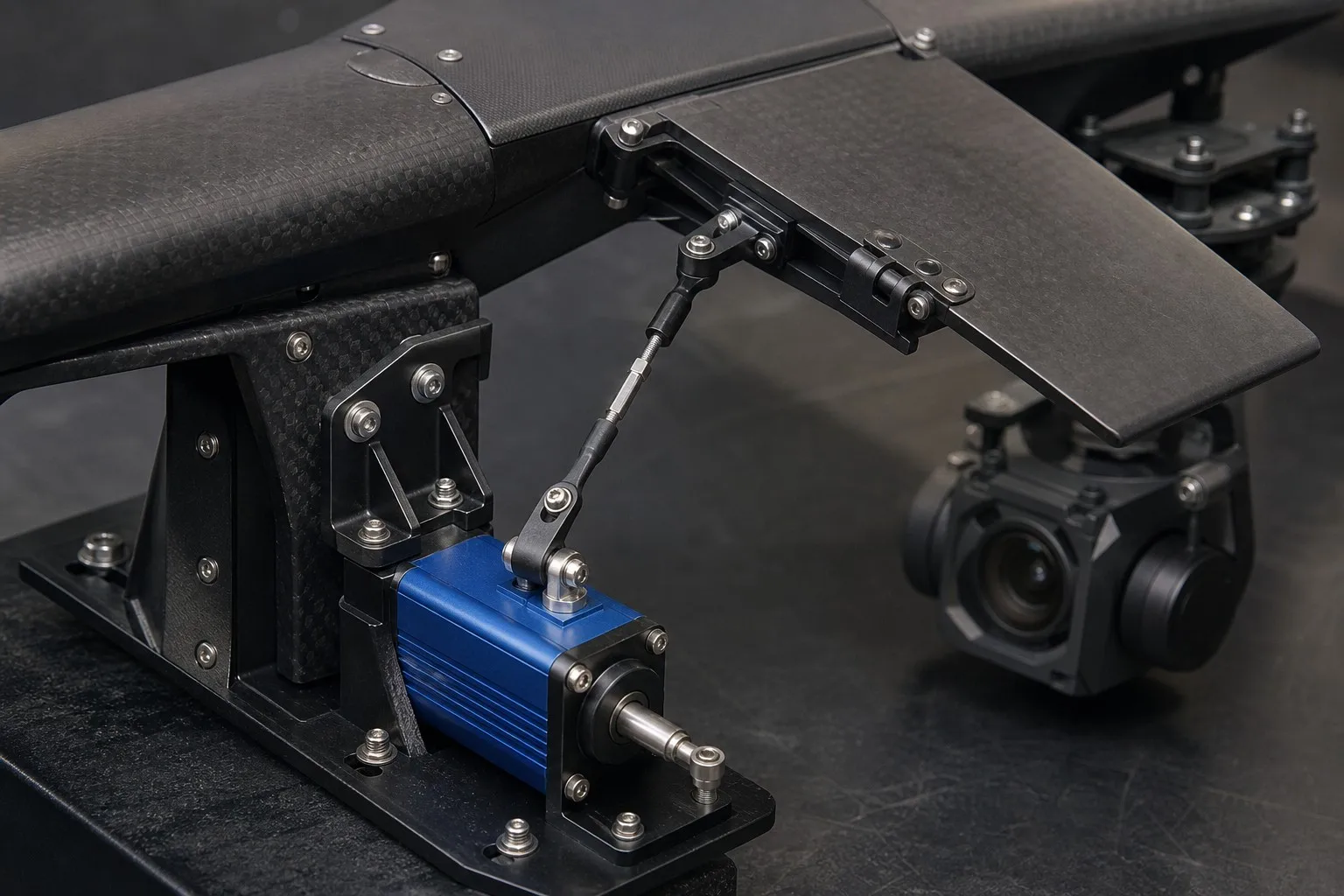
This system view explains the relationship between Feiyida UAV platforms and XQ-POWER mechanical and electronic products. Feiyida focuses on industrial intelligent UAVs and core UAV components, while XQ-POWER covers servos, brushless digital servos, digital servos, robot servos, RC servos, ESCs, motors, power-control systems, precision sensors, and related intelligent mechanical and electrical equipment. The value of these product areas is not simply that they can be listed in the same catalog. Their value is that they address different layers of a complete intelligent machine.
The purpose of this article is to explain how those layers interact, why system boundaries matter, and how engineers and procurement teams can move from a platform-level requirement to a verifiable electromechanical solution. The same principles can also apply to industrial automation, mobile machines, robotic equipment, and other products that combine mechanical movement with electronic intelligence.
1. Why an Industrial UAV Should Be Treated as Intelligent Equipment
A consumer drone can often be described by a short list of headline features: flight time, camera, range, and control method. Industrial equipment requires a broader description because the aircraft is part of a repeatable process. It must perform a defined task, carry or control a payload, communicate status, respond to abnormal conditions, and be maintained over a service period.
The platform is therefore only one layer of the solution. Its performance depends on the relationship between the airframe, motors, ESCs, batteries, flight-control system, servos, sensors, data link, payload, and operating procedure. A failure that appears to be a flight problem may originate in a connector, power rail, actuator linkage, sensor installation, thermal condition, or software configuration.
This is why intelligent equipment should be evaluated through four questions:
- What must move? Identify motors, control surfaces, landing mechanisms, gimbals, release mechanisms, valves, or other mechanical elements.
- What must be measured? Identify position, angle, temperature, current, voltage, speed, pressure, navigation state, or payload status.
- What must be controlled? Define the commands, response time, accuracy, sequence, and safe state for each mechanism.
- What must be verified? Define the test conditions, acceptance criteria, logs, maintenance records, and operator actions.
A UAV platform becomes intelligent equipment when these functions are connected into a repeatable operating system. The aircraft does not merely generate thrust; it senses its condition, interprets commands, coordinates mechanical and electronic subsystems, and produces mission data that can be reviewed after the task.
This system perspective also changes procurement. Instead of asking only for a product with a certain torque, voltage, payload, or range, the buyer can ask how the complete equipment will be integrated, tested, serviced, and supported.
2. The Mechanical Layer: Structure, Motion, and Load Paths
The mechanical layer gives an intelligent machine its physical form and determines how forces travel through the system. In a UAV, it includes the airframe, motor mounts, propeller assemblies, landing structures, control surfaces, payload mounts, gimbals, actuator brackets, and service interfaces. In other equipment, it may include robot links, steering assemblies, clamps, valves, or access mechanisms.
Mechanical design should begin with the complete load path, not with an actuator label. A servo may produce motion, but the surrounding bracket, arm, linkage, hinge, bearing, fastener, and structure determine whether that motion becomes useful and repeatable. If the structure flexes, the actuator may reach its commanded position while the mechanism fails to hold the required physical state.
Several mechanical questions should be answered early:
- Where does the external load enter the mechanism?
- Which parts carry radial, axial, bending, or impact loads?
- Does the actuator output shaft provide motion only, or is it incorrectly being used as a structural bearing?
- What is the center of gravity of the moving load?
- What are the hard stops, travel limits, and over-center conditions?
- How will wear, backlash, contamination, vibration, and temperature affect movement?
- Can the mechanism be inspected, removed, and replaced in the field?
For UAV platforms, weight and packaging make these questions especially important. A stronger bracket, longer cable, larger actuator, or additional sensor may improve one function while reducing available payload or changing the center of gravity. The correct design is therefore a system trade-off rather than a search for the largest available component.
The mechanical layer also defines serviceability. Intelligent equipment should not require the operator to dismantle unrelated systems to replace a high-wear component. Access covers, connector routing, fastener selection, alignment features, and replaceable modules all influence the real cost of ownership.
3. The Actuation Layer: Turning Commands Into Physical Motion
Actuators connect electronic decisions to mechanical outcomes. They may control aerodynamic surfaces, gimbals, landing mechanisms, payload release systems, valves, steering assemblies, robot joints, or industrial tooling. Their job is not simply to rotate; it is to produce a defined physical state under a defined load, speed, duty cycle, and environmental condition.
The actuation requirement should describe the mechanism in terms of states and transitions. For example, a payload mechanism may need to remain locked, release on command, confirm the released state, and return to a safe position. A gimbal may need to hold a payload angle while the platform vibrates. A control surface may need to follow commanded movement without excessive backlash.
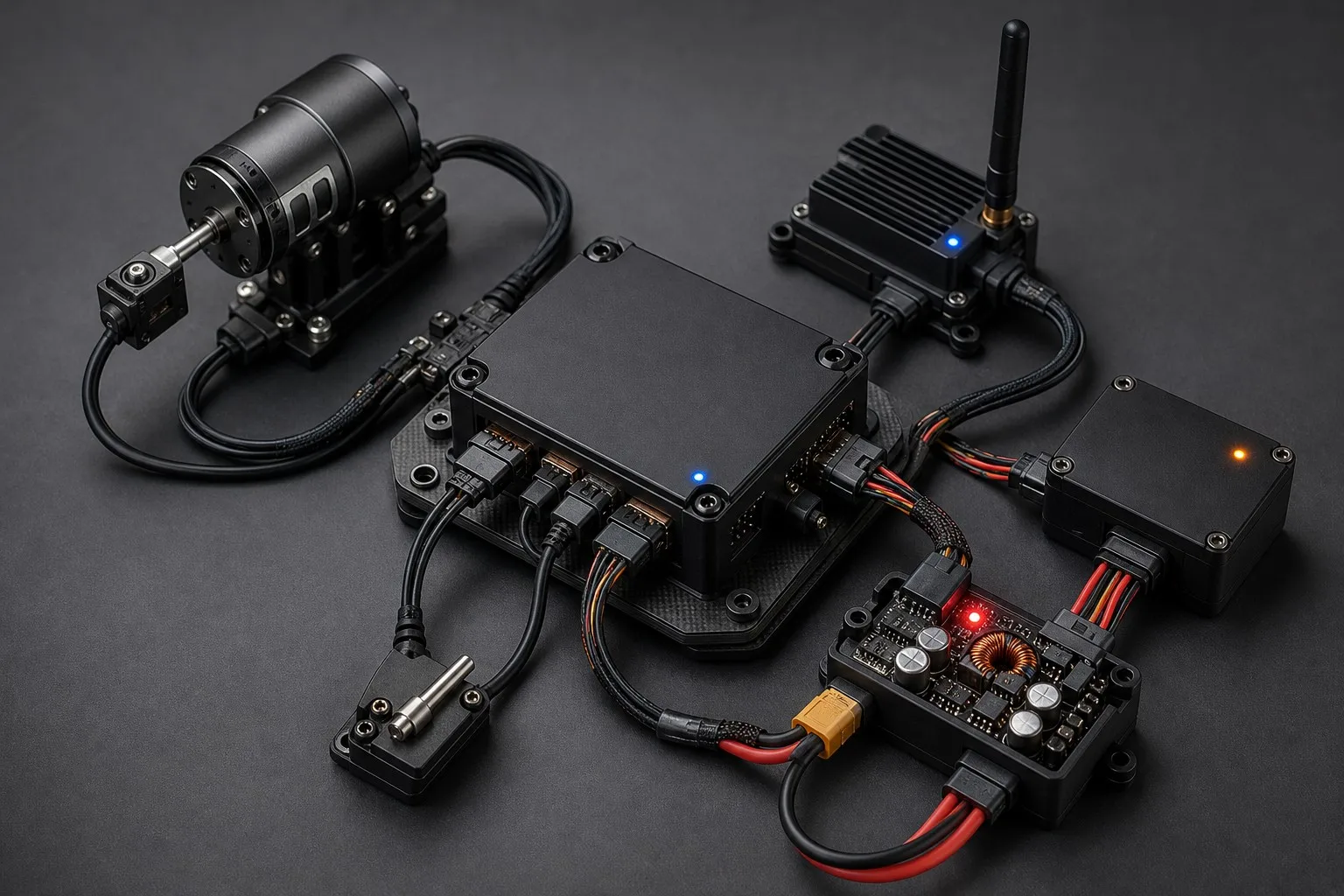
A practical actuator specification may include:
- Required output force or torque at the actual linkage;
- Moving mass and center-of-gravity offset;
- Angular or linear travel;
- Required speed and acceleration;
- Holding time and duty cycle;
- Backlash and repeatability limits;
- Input voltage and power budget;
- Control signal or communication interface;
- Position or health feedback;
- Mechanical mounting and output interface;
- Temperature, vibration, moisture, dust, or chemical exposure;
- Safe state after power or communication loss.
Different applications may require different actuator architectures. A compact PWM servo may be appropriate for a simple command path. A digital bus actuator may be useful when a system needs multiple nodes, status information, or reduced point-to-point wiring. A brushless actuator may be considered where duty cycle, response, thermal behavior, or service requirements justify it. The correct decision depends on the application and the documented interface, not on the technology label alone.
XQ-POWER's published product positioning spans servo, brushless digital servo, digital servo, robot servo, RC servo, industrial large-torque servo, and other motion-control products. Actuator selection should follow the mechanism and system architecture. A UAV gimbal, a robot joint, a control surface, and an industrial clamp may all use a servo-like device, but their load paths, motion profiles, safety states, and validation plans are different.
4. The Sensing Layer: Giving Equipment a Measurable State
Electronic control is only as reliable as the information available to it. Sensors provide the evidence needed to determine whether a machine is in the commanded state, approaching a limit, overheating, losing power, or experiencing abnormal behavior.
In a UAV, sensing may include attitude, position, altitude, speed, battery voltage, current, temperature, actuator position, payload status, and communication quality. In intelligent mechanical equipment, sensing may also include joint angle, clamping force, valve position, wheel position, pressure, proximity, or enclosure condition.
The key distinction is between a commanded state and an achieved state. A controller can send a command to move an actuator, but that command does not prove that the mechanism moved correctly. A position sensor, limit switch, current signature, or other feedback path may be required to confirm the physical result.
Sensor integration should address four issues:
- Measurement suitability: Is the sensor measuring the variable that matters, or only a convenient proxy?
- Installation quality: Is the sensor protected from vibration, heat, electromagnetic noise, contamination, and mechanical interference?
- Data interpretation: Does the controller distinguish normal variation from a real fault?
- Failure response: What happens when the sensor is missing, implausible, delayed, or inconsistent with another source?
Feedback can also support maintenance. A gradual increase in actuator current may indicate friction, misalignment, or a growing mechanical load. A change in temperature may reveal blocked airflow, excessive duty cycle, or a failing component. Repeated position errors may indicate backlash, loose mounting, or a calibration problem.
Precision sensors should therefore be considered part of the machine's operational evidence. They help the operator and service team understand whether the equipment is healthy, whether a mission should continue, and whether a component should be inspected before the next cycle.
5. The Electronic-Control Layer: Coordinating the Machine
The electronic-control layer converts mission intent and sensor data into coordinated actions. It may include the flight controller, motor and servo control, power monitoring, communication interfaces, embedded logic, onboard computing, and ground-control software.
Good control architecture begins with clear ownership. Each function should have a defined source and destination:
- Which controller commands the motor or actuator?
- Which device reads position feedback?
- Which system manages the payload?
- Which channel carries telemetry?
- Which module detects a fault?
- Which device applies the safe-state response?
- Which system records the event for later analysis?
Without these boundaries, two controllers may issue conflicting commands, a fault may be reported without an action, or a payload may continue moving after the aircraft has entered a recovery mode. Clear interface diagrams are often more valuable than general claims about intelligence.
Electronic control also has to manage timing. A slow status update may be adequate for a maintenance display but unsuitable for fast mechanical motion. A control system should define priority, update behavior, timeout handling, and recovery after communication interruption.
Power is part of the control architecture. Motors, ESCs, servos, sensors, radios, cameras, and computers may have different voltage and current requirements. Power integrity problems can appear as control errors, sensor resets, communication loss, or intermittent actuator behavior.
6. The Power Layer: Supplying Motion and Intelligence
Power systems connect the energy source to both the high-load and low-signal parts of the machine. In UAVs, propulsion consumes substantial energy while flight-control electronics, servos, sensors, radios, cameras, and computers require stable electrical conditions.
A power plan should separate at least four questions:
- What energy source is available?
- What voltage does each subsystem require?
- What current and transient load does each subsystem create?
- What reserve and protection are required when the system is near its limit?
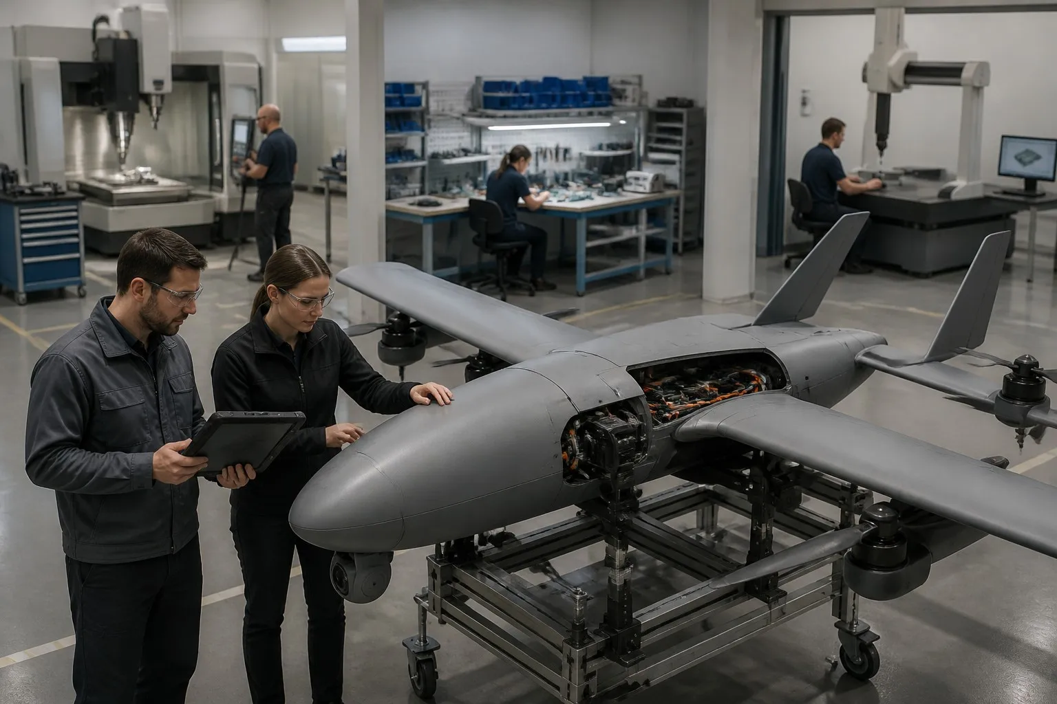
The power layer should be tested under realistic conditions. Measure wiring, connectors, regulators, batteries, ESCs, and actuators together while recording voltage, current, temperature, and abnormal events. Thermal behavior is closely connected to power: electrical losses become heat in motors, ESCs, regulators, actuators, and enclosures.
Power design also affects maintenance and diagnosis. Clearly separated power paths, accessible test points, labeled connectors, configuration records, and event logs make it easier to identify whether a fault originated in the battery, regulator, wiring, control device, actuator, or load. XQ-POWER's company profile identifies ESCs, motors, and power-control systems among its product areas, which connect naturally with the UAV and intelligent-equipment system view.
7. From Components to a Verified System Architecture
The transition from a product catalog to an intelligent system happens during integration. Components must be connected according to a documented architecture, configured with compatible parameters, and tested under the conditions that represent the intended mission.
| Layer | Main question | Evidence to request |
|---|---|---|
| Mechanical | Can the structure carry and guide the load? | Drawings, load cases, alignment checks |
| Actuation | Can the mechanism reach and hold the required state? | Motion profile, duty-cycle test, travel verification |
| Sensing | Can the system detect its actual condition? | Sensor map, calibration record, plausibility checks |
| Electronic control | Can commands and feedback be coordinated? | Interface diagram, firmware and configuration record |
| Power | Can the system supply motion and electronics together? | Voltage, current, temperature, transient test |
| Communication | Can the operator receive essential status? | Link test, timeout behavior, event logs |
| Service | Can the equipment be inspected and repaired? | Maintenance procedure, spare-parts plan, version record |
The evidence should be tied to the final configuration. A bench test on one actuator does not prove the behavior of a mechanism with a different linkage. A radio test without the payload does not prove the performance of the complete aircraft. A sample unit that works in a laboratory does not automatically prove batch consistency.
A staged validation process reduces uncertainty:
- Review the requirements and interface ownership.
- Verify mechanical fit, wiring, connectors, and basic power behavior.
- Test each actuator and sensor independently.
- Integrate control, feedback, payload, and communication functions.
- Run loaded ground or bench tests.
- Test defined fault and recovery conditions.
- Perform representative operation with the final configuration.
- Record results and freeze the approved configuration.
8. Manufacturing Capability Is Part of System Capability
Intelligent equipment depends on more than design intent. It also depends on whether the manufacturer can repeatedly build, inspect, configure, and support the system. A design that cannot be produced consistently or serviced efficiently is not a complete industrial solution.
The company profile for Shenzhen XQ-POWER Technology Co., LTD. describes a business founded in 2010 and identifies a manufacturing environment that includes a precision manufacturing model workshop, CNC machining center, electronic workshop, quality-control center, and injection molding workshop. These capabilities are relevant because intelligent mechanical and electrical equipment combines structural parts, machined components, electronic assemblies, molded parts, sensors, actuators, and software or configuration work.
- Can mechanical dimensions be held consistently across batches?
- Are electronic assemblies tested before final integration?
- Are critical actuator and sensor parameters recorded?
- Can the manufacturer trace changes to parts, firmware, or configuration?
- Are production tests linked to the customer's acceptance criteria?
- Can replacement parts remain compatible over the expected service period?
- Is there a defined process for engineering changes?
Quality is not a final visual inspection. It is a chain that begins with requirements and continues through design, material selection, machining, electronics, assembly, configuration, testing, packing, delivery, and service.
9. How Customers Should Define an Integrated Project
Customers can make an industrial equipment project more efficient by defining the mission and system interfaces before requesting a quotation. A useful project brief should include:
- Intended application and operating environment;
- Platform or machine type;
- Payload or moving load;
- Required movements and mechanical states;
- Duty cycle and expected operating hours;
- Required sensors and feedback;
- Power source and voltage architecture;
- Control, communication, and software interfaces;
- Safety and recovery behavior;
- Space, weight, and mounting constraints;
- Required documents and test evidence;
- Prototype, pilot, and production quantities;
- Service, spare-parts, and change-control expectations.
The request should distinguish required specifications from preferred specifications and define acceptance evidence. An integrated project is most successful when the customer and manufacturer share a clear responsibility matrix before a failure occurs.
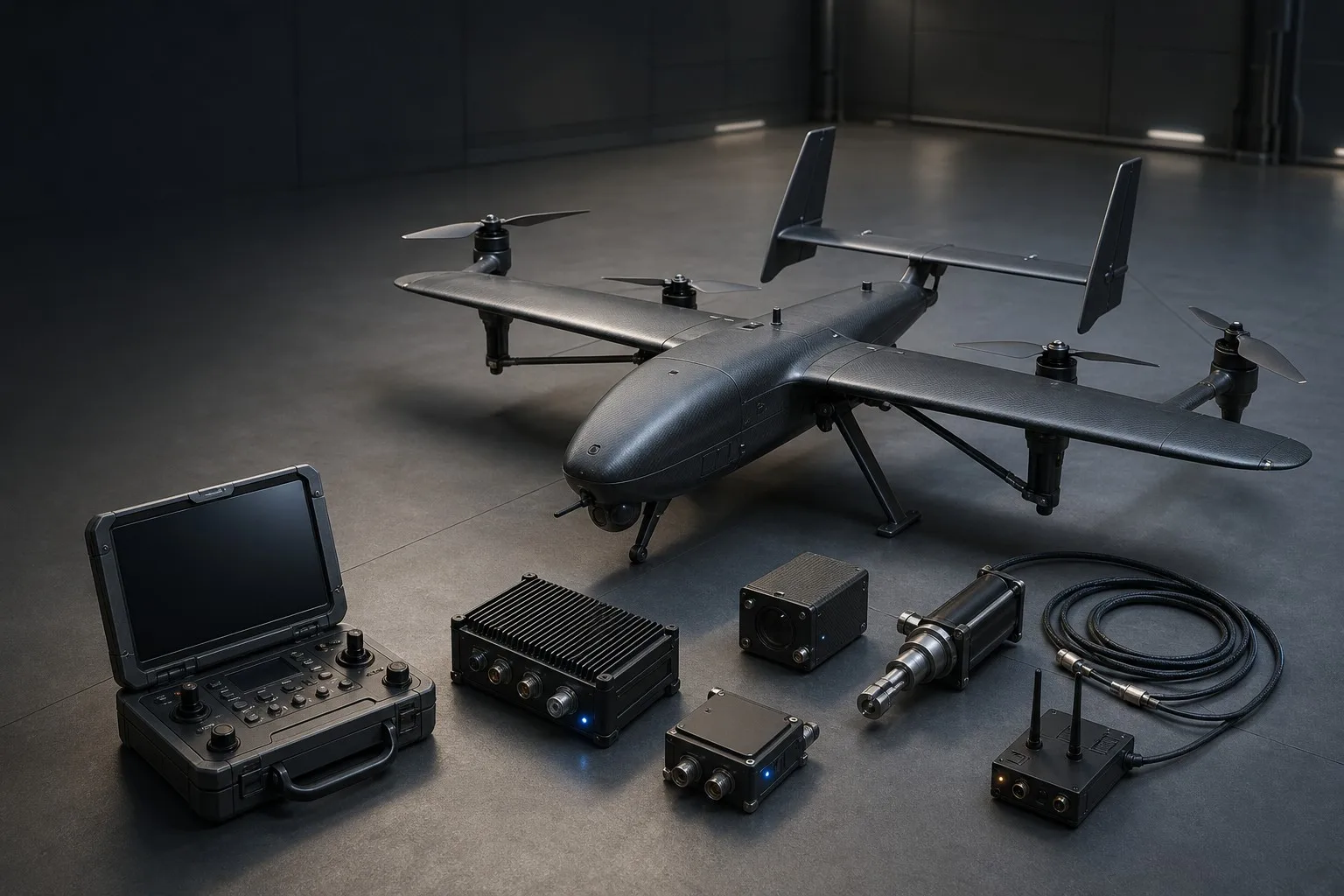
Conclusion: Intelligent Equipment Is Built at the Interfaces
The difference between a collection of components and intelligent equipment is the quality of the interfaces between them. The airframe must work with the propulsion system. The actuator must work with the mechanism. The sensor must measure the state that matters. The controller must interpret feedback and apply the correct response. The power system must support both high-load movement and sensitive electronics. The manufacturer must then build and verify the same system consistently.
Feiyida's industrial UAV focus and XQ-POWER's servo, motor, ESC, sensor, and power-control product areas represent complementary layers of this engineering problem. The right system is created by defining the mission, assigning interface ownership, validating the load and control paths, and preserving the approved configuration through production and service.
For customers, the practical lesson is simple: describe the complete task rather than asking for an isolated component. For manufacturers and system integrators, the responsibility is to connect mechanical design, electronics, sensing, power, control, manufacturing, and support into one verifiable equipment solution.
Planning an integrated UAV or intelligent electromechanical project? Contact FEIYIDA and XQ-POWER with the application, mechanical movements, load, power system, interfaces, environment, production quantity, and required test evidence for a configuration review.
Frequently Asked Questions
What is intelligent electromechanical equipment?
Intelligent electromechanical equipment combines mechanical structures and motion with electronic control, sensing, power management, communication, and software or configuration logic. It can act on commands, measure its condition, respond to faults, and produce operational information for control and maintenance.
Why is an industrial UAV more than an airframe?
An industrial UAV must perform a repeatable mission. Its result depends on propulsion, flight control, servos, sensors, payloads, data links, batteries, ground equipment, configuration, and service procedures. The airframe is the platform, but the mission is delivered by the complete system.
What is the difference between commanded state and achieved state?
A commanded state is what the controller asks a mechanism to do. An achieved state is what the mechanism physically reaches and holds. Feedback, position sensing, limit detection, current monitoring, or other verification may be required to confirm that the commanded state was actually achieved.
How do servos and actuators fit into an intelligent equipment system?
They convert electronic commands into physical movement. Their suitability depends on the complete mechanism, including load path, travel, speed, duty cycle, mounting, power, control interface, environment, feedback, and safe behavior after power or communication loss.
Why should power be designed with control and mechanics together?
Motors, ESCs, actuators, sensors, radios, cameras, and computers can create different electrical loads and transients. A power problem can appear as a mechanical, sensor, or communication fault. Testing these systems together reveals voltage drop, heat, wiring, and connector problems that isolated component tests may miss.
What should a customer include in an integrated equipment request?
Include the application, environment, platform, loads, required movement, duty cycle, power source, interfaces, sensors, feedback, safety behavior, mounting constraints, production quantity, documentation, test evidence, and service expectations.
Does manufacturing capability affect intelligent equipment performance?
Yes. Machining accuracy, electronic assembly, molding, calibration, testing, configuration control, and engineering-change management can all affect system consistency. A successful prototype is not enough if the same mechanical and electronic behavior cannot be reproduced in production.
Which industries can use this system approach?
The approach applies to industrial UAVs, mobile equipment, robotic mechanisms, automation, inspection platforms, intelligent tools, and other products that combine mechanical movement with electronic control and sensing.
- FEIYIDA home page
- Company Profile
- Product Center
- Fixed-Wing Plane product category
- XQ-POWER SERVO product category
- Multi-Rotors product category
- Gimbal Camera product category
- Video & Data Link product category
- Battery & Charger product category
- Flight Controller product category
- More Accessories product category
- How to Operate UAVs in Harsh Environments
- Industrial Servo OEM/ODM Specification Checklist
Keywords:
Consult Immediately
If you are interested in our products, please leave your email and we will contact you as soon as possible. Thank you!



Company Address: 1 Bldg,Tonghe Industrial park,N26.Fuping Road,Longgang District Shenzhen City ,Guangdong Province,China.


© 2024~ Shenzhen XQ-POWER Technology Co., LTD. All rights reserved.