

20
2026
-
10
How to Plan an Industrial UAV Mapping Project from Site Survey to Final Data
A practical guide to planning an industrial UAV mapping project, covering site survey, platform selection, mission design, reference data, field capture, quality control, processing, and final delivery.


Author:
How to Plan an Industrial UAV Mapping Project from Site Survey to Final Data
An industrial UAV mapping project should be planned as a data-delivery workflow, not as a single flight. The aircraft is only one part of the project. A reliable result depends on the site survey, mapping objective, ground conditions, route design, aircraft and payload configuration, weather plan, field checks, image or sensor capture, quality control, processing, and final data handover.
The most important planning decision is to define what the final data must support before choosing the flight method. A project may require an orthomosaic, terrain model, topographic surface, inspection record, volume estimate, change comparison, or a map for engineering review. Each output creates different requirements for coverage, overlap, control, image quality, positioning, processing, and acceptance.
This guide presents a practical industrial UAV mapping workflow from site survey to final data. It is designed for mapping, construction, infrastructure, land management, quarry, inspection, and other professional applications. It does not assign universal accuracy, coverage, altitude, or flight-time values. Those values must be set from the project brief, site conditions, equipment documentation, local requirements, and the chosen processing method.
1. Define the Final Mapping Deliverable First
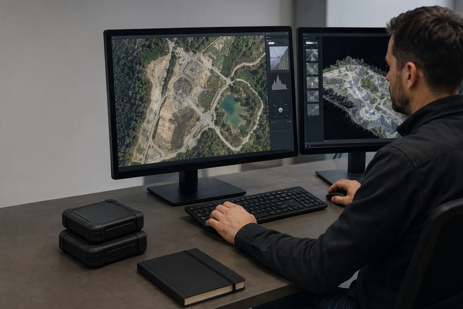
A mapping project should begin with the final decision the data needs to support. “Create a map” is not a complete requirement because different stakeholders may mean different outputs, scales, coordinate systems, update cycles, and levels of detail.
Write the deliverable in a form that can be checked. Examples include:
- An orthomosaic for visual progress review;
- A digital surface model for terrain or construction analysis;
- A point cloud for engineering coordination;
- A three-dimensional model for inspection or measurement;
- A stockpile or excavation volume report;
- A corridor map for roads, pipelines, or power infrastructure;
- A change-detection comparison between two survey dates;
- A georeferenced image set for a customer or internal GIS system.
For every output, record the expected coordinate reference system, vertical reference, file format, map boundary, level of detail, delivery date, review method, and acceptance criteria. Confirm who will use the data and what decision it will support. An engineering team may need measurable geometry, while a project manager may need a clear progress comparison. A maintenance team may need a repeatable view of defects rather than a general-area map.
Also distinguish between the information that must be measured and the information that is only useful for context. This helps determine whether the project needs a high-detail local survey, a larger-area overview, a corridor mission, or several separate data products.
The final deliverable should influence the field plan from the beginning. If the customer requires repeat surveys, document the area boundary, capture direction, control strategy, and processing settings so later missions can be compared consistently. If the customer needs a measurement that depends on visible edges or surfaces, identify possible occlusions before the aircraft is launched.
A clear output definition prevents a common failure: collecting attractive images that cannot be processed into the required engineering or operational data.
2. Conduct a Structured Site Survey
The site survey converts a map or customer description into field information. It should identify the physical, operational, environmental, and data risks that could affect the mission.
Before visiting the site, collect available drawings, previous surveys, satellite imagery, site rules, access instructions, known hazards, and the contact details of the person responsible for the work area. On site, confirm whether the actual conditions match the available documents.
Record the following:
- Site boundary and areas that must be included or excluded;
- Terrain, buildings, structures, vegetation, water, and restricted zones;
- Elevation changes and possible line-of-sight limitations;
- Suitable launch, recovery, parking, and equipment-preparation areas;
- People, vehicles, cranes, machinery, power lines, and other moving hazards;
- Reflective, repetitive, dark, transparent, or water surfaces;
- Wind exposure, dust, rain, glare, shadows, and likely weather changes;
- Communication coverage and ground-station placement;
- Battery preparation, charging, storage, and transport arrangements;
- Access, security, personal protective equipment, and emergency procedures;
- The timing of operations that may change the site between flights.
The site survey should also identify where the aircraft cannot safely collect data. Tall structures, narrow corridors, dense vegetation, steep faces, reflective roofs, and areas with moving equipment may require separate routes or additional observation. A mapping boundary should not be treated as a promise that every point inside it can be captured with equal quality.
For industrial projects, the site survey is also a coordination activity. Confirm who controls the worksite, who can stop machinery, who can approve the launch point, who will receive the final data, and who has authority to change the mission. These responsibilities should be recorded before field work begins.
The output of the site survey should be a short mission brief containing a map, hazards, access plan, proposed launch points, communication plan, weather constraints, data requirements, and open questions. Do not proceed to detailed route design while important site assumptions remain undocumented.
3. Choose the Mapping Method and Platform
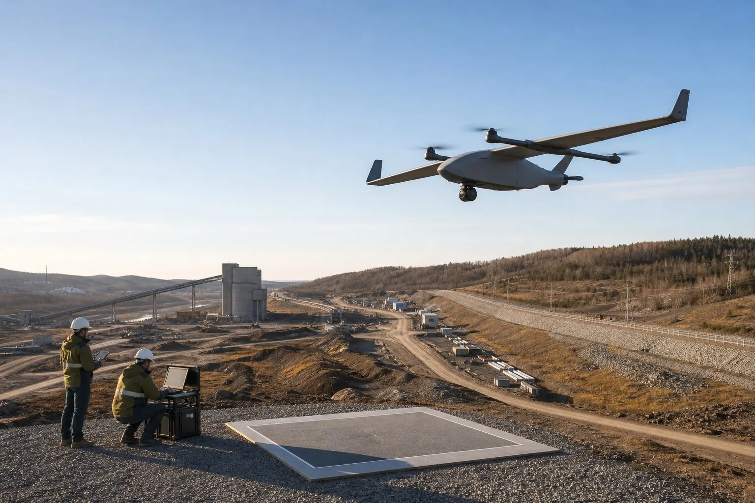
The mapping method should follow the deliverable and site conditions. An aircraft that is suitable for a large open area may not be the best choice for a confined industrial site, a linear corridor, a steep quarry, or a location with frequent obstacles.
Consider the platform in relation to the mission:
- Multirotor platforms: Useful when the site requires flexible launch and recovery, lower-speed inspection, local detailed capture, or frequent repositioning.
- Fixed-wing platforms: Useful when the project covers a larger area and the mission benefits from efficient forward flight, provided that the site supports the required launch and recovery process.
- Hybrid VTOL platforms: Useful when a project needs vertical takeoff and landing flexibility together with fixed-wing cruise behavior, subject to the aircraft's documented configuration and operational limits.
This is not a universal ranking. The correct platform depends on site size, route geometry, terrain, launch conditions, wind, payload, required data density, operator workflow, and recovery options.
The payload also matters. A mapping camera, stabilized camera, thermal module, optical payload, or combined sensor package creates different data and integration requirements. Confirm the payload's mounting, power, storage, trigger or synchronization method, field of view, image format, metadata, and relationship with the flight-control and data-link systems.
FEIYIDA's official product structure separates Fixed-Wing Plane, Multi-Rotors, Gimbal Camera, Video & Data Link, Battery & Charger, Flight Controller, and More Accessories. These categories are useful for organizing the project conversation, but they should not be treated as a complete system recommendation without reviewing the actual site and deliverable.
Before selecting equipment, prepare a system-level table that maps each project need to an aircraft, payload, control, communication, power, and data requirement. This makes missing interfaces visible before the team arrives on site.
4. Design the Mission and Route
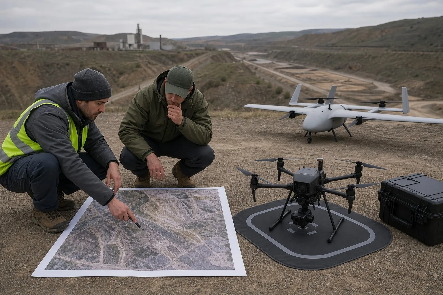
Route design should connect the site boundary, capture geometry, aircraft behavior, safety constraints, and data quality requirements. It should not be based only on the shortest route or the largest possible area per flight.
Define the mapping block or corridor first. Then identify the required flight direction, turning areas, takeoff and landing points, exclusion zones, and potential emergency landing locations. For terrain with significant elevation changes, assess whether a constant-height route, terrain-following plan, or separate sub-areas are required. The correct choice depends on the aircraft, flight-control system, terrain data, and project objective.
Route design should account for:
- Required image overlap or sensor sampling;
- Ground detail and desired output resolution;
- Terrain and structure height;
- Sun angle, shadows, glare, and reflective surfaces;
- Wind direction and expected gusts;
- Battery and mission segmentation;
- Communication and telemetry coverage;
- Safe turns and recovery paths;
- Areas requiring cross-grid, oblique, or close-range capture;
- Changes in site activity during the mission.
For a corridor project, divide the route into logical sections and define how each section will be named and checked. For a stockpile, excavation, or complex structure, consider whether an additional oblique or perimeter capture is needed to reduce hidden surfaces. For a repeat survey, preserve the route logic and camera or sensor configuration so later datasets remain comparable.
The mission plan should include a pre-flight route review. The operator should know where the aircraft will be, where it cannot go, how the mission will be paused, and where it will recover if weather, people, machinery, or communication conditions change.
A route is ready for field use only when it works both as a data-collection plan and as a safe operating plan. If the route produces excellent theoretical coverage but leaves no recovery option, it is not a complete industrial mission.
5. Plan Ground Control, Positioning, and Reference Data
Mapping quality depends on more than image count. The project must define how the collected data will be located, aligned, checked, and compared with other information.
Select the positioning and reference method according to the deliverable and required acceptance criteria. The plan may involve onboard positioning, ground control points, checkpoints, surveyed reference marks, known site coordinates, or a combination of methods. Do not assume that one method is appropriate for every project.
Document:
- Horizontal and vertical coordinate reference systems;
- Units and axis conventions;
- Required geoid or height treatment where applicable;
- Ground-control and checkpoint locations;
- Marking, visibility, protection, and measurement records;
- Survey equipment and field notes;
- Data naming and relationship between points and imagery;
- Independent checks that are not used to adjust the result;
- How the final coordinate system will be communicated to the customer.
Control points should be placed where they are visible, stable, distributed across the site, and unlikely to be moved by construction or daily operations. Checkpoints should be planned separately from adjustment points when the project requires an independent quality assessment. The number and placement should be based on site geometry and project requirements rather than copied from a generic template.
For repeat mapping, preserve the reference strategy. A later comparison can be misleading if the coordinate system, control method, area boundary, or processing assumptions change between surveys.
Ground-control planning also affects field time. Allow time for placement, measurement, recovery, documentation, and verification. A control point that is poorly visible, incorrectly recorded, or removed before capture can create a data problem that is difficult to correct during processing.
The final report should state how the dataset was referenced and checked. Avoid describing a map as “accurate” without explaining the measurement basis and the acceptance method.
6. Prepare Aircraft, Payload, and Field Equipment
The mapping aircraft should be prepared as a complete data-collection system. A flight-ready platform is not necessarily a mapping-ready platform. The camera, storage, trigger, positioning source, flight controller, data link, batteries, and ground equipment must work together.
Before leaving for the site, confirm:
- Aircraft configuration and software version;
- Payload mounting and lens or sensor condition;
- Camera settings, storage capacity, and file format;
- Time synchronization and metadata behavior;
- Battery identification, condition, and charging status;
- Flight-control and navigation configuration;
- Data-link and ground-station operation;
- Spare batteries, storage media, cables, propellers, tools, and protective cases;
- Field computer, backup storage, and power supply;
- Required forms, maps, permits, and safety equipment.
The preparation checklist should identify which settings are fixed for the project and which can change in the field. Uncontrolled changes to camera exposure, capture interval, focus, image format, route, or positioning settings can make datasets inconsistent or unusable.
Run a short pre-deployment test using the same configuration intended for the site. Confirm that images or sensor files are recorded correctly, metadata is present, the flight controller reports expected status, the data link remains available, and the ground station can save mission information.
Equipment should be packed according to workflow, not merely by component type. The operator should be able to prepare the aircraft, establish the ground station, verify the payload, place or check control points, perform the safety briefing, and recover the data without searching through unrelated cases.
For industrial work, maintain a configuration record. Note the aircraft identifier, payload identifier, battery identifier, software or firmware version, route version, and any changes made before or during the project. Configuration history is part of the dataset's credibility.
7. Execute Field Capture With Quality Checks
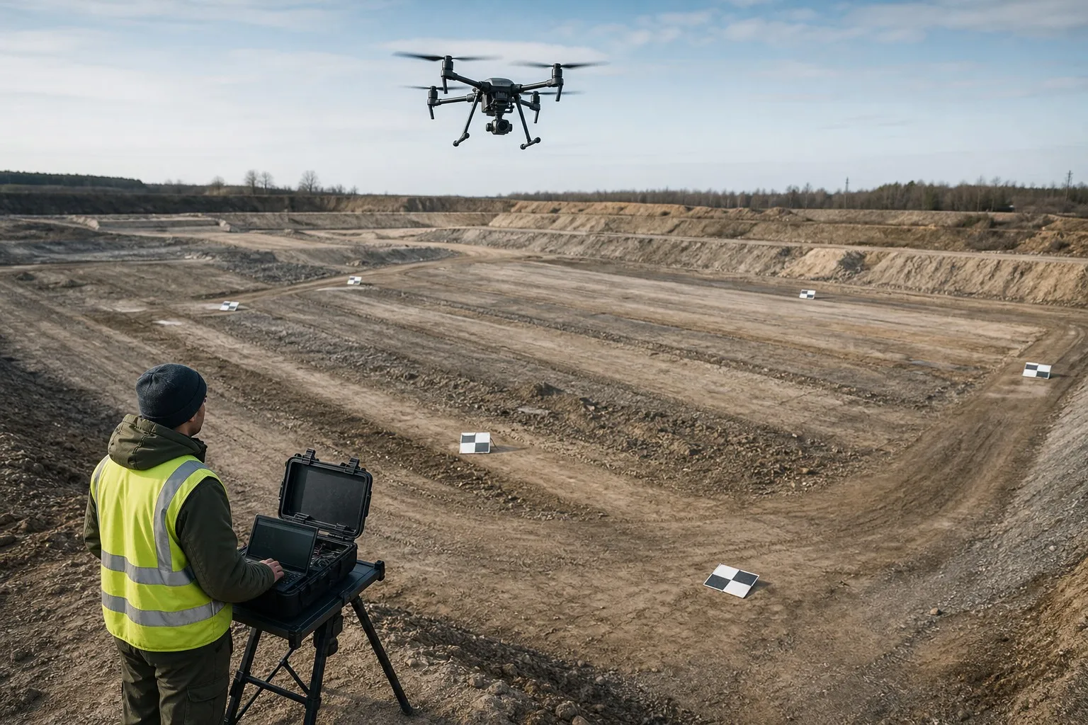
Field capture should be managed as a controlled production process. The team should not wait until the end of the day to discover that images were missing, blurred, incorrectly exposed, poorly positioned, or recorded with the wrong settings.
Before each mission, repeat the site-specific safety review. Confirm the launch area, people and vehicle status, weather, route, battery, storage, payload, communication, control points, and emergency plan. Use a mission identifier that connects the flight log, image files, operator notes, and battery record.
During the mission, monitor the information that affects data quality and safety:
- Aircraft position and route progress;
- Battery state and expected reserve;
- Communication and telemetry;
- Camera or sensor status;
- Storage and capture confirmation;
- Wind, visibility, light, and site activity;
- Unexpected obstacles or restricted areas;
- Warnings, pauses, and operator interventions.
After landing, perform an immediate data check before releasing the aircraft for another flight. Confirm that the expected files exist, the mission identifier is recorded, the images or sensor data are readable, the coverage matches the route, and no obvious section requires recapture.
Use a simple field quality gate:
- Coverage: Was the planned area or corridor captured?
- Completeness: Are the files and metadata present?
- Clarity: Are images or sensor records usable?
- Geometry: Is the capture pattern suitable for the intended output?
- Reference: Are control and checkpoint records complete?
- Repeatability: Can another team understand how the mission was performed?
If a problem is found, decide while the aircraft and crew are still on site whether to repeat the section. A short recapture may be far less expensive than returning after the site changes or equipment is demobilized.
8. Process and Quality-Control the Data
Processing should begin with organized, verified inputs. Do not import every file into a project without first identifying the flight, route, payload, control data, and known exceptions.
Create a project structure that separates:
- Original aircraft or sensor files;
- Flight logs and mission records;
- Control-point and checkpoint data;
- Processing project files;
- Intermediate outputs;
- Quality-control notes;
- Final deliverables;
- Customer revisions and approved versions.
Keep original data read-only. Work from copies or controlled processing directories so the source files remain available if settings must be changed. Use consistent naming that identifies the site, date, mission, sensor, and processing version.
Quality control should review both technical and visual results. Check for missing areas, duplicated or misordered data, blurred images, exposure changes, gaps, distortions, alignment problems, incorrect reference systems, and visible artifacts. Where the project requires measurement confidence, review control and checkpoint residuals or other documented quality indicators using the method agreed in the project brief.
Processing settings should be recorded. The final dataset should be reproducible enough that the team can explain which source data, control information, software version, coordinate system, and major parameters were used. This is especially important for repeat surveys and customer disputes.
Do not hide a data limitation by presenting a visually attractive model. If vegetation, water, shadow, dust, motion, reflective surfaces, occlusion, or insufficient capture affects a part of the site, identify the limitation and state whether a recapture, additional sensor, or different survey method is required.
Quality control is not a single final glance. It begins in the field and continues through processing, review, export, and delivery.
9. Deliver Final Data as a Managed Package
The final delivery should contain more than a single map file. Customers need enough context to understand what was collected, how it was processed, what it represents, and what limitations apply.
A practical delivery package may contain:
- Final orthomosaic, model, point cloud, map, or report;
- Coordinate reference and units;
- Site boundary and coverage statement;
- Date and time of capture;
- Aircraft and payload description at the appropriate level;
- Processing software and major workflow notes;
- Control or checkpoint summary when applicable;
- Quality-control result;
- Known gaps, occlusions, or limitations;
- File format and viewing instructions;
- Revision number and approval status;
- Contact for technical questions.
For recurring projects, define a naming and versioning standard. A customer should be able to distinguish a preliminary export from an approved final file and compare one survey date with another. Avoid replacing files without recording what changed.
Data security should also be part of the handover. Confirm who can access original images, processed products, reports, and backups. Store the data according to the customer's retention, privacy, and operational requirements. If sensitive infrastructure or industrial information is involved, define how data is transferred and who may reuse it.
The final delivery should be reviewed against the original brief. Confirm that every required output exists, opens correctly, uses the requested reference system, covers the agreed area, and contains the expected metadata or documentation. Only then should the project be marked complete.
10. Improve the Workflow for Repeat Mapping Projects
A mature mapping operation improves by comparing projects, not by treating every mission as a one-time event. After delivery, review the field and processing records to identify wasted time, repeated failures, unclear responsibilities, and opportunities for standardization.
Useful review questions include:
- Did the site survey identify the actual hazards?
- Was the selected platform appropriate for the site and output?
- Did the route provide the required coverage and geometry?
- Were control and checkpoint records complete?
- How often was recapture required, and why?
- Which equipment or settings caused delays?
- Was the data organized consistently?
- Could the customer use the final files without additional explanation?
- What should be changed before the next survey?
Build reusable templates for mission briefs, safety reviews, control-point records, field quality gates, data directories, processing notes, and delivery reports. Standardization should reduce preventable variation without forcing every site into the same flight pattern.
For repeat surveys, preserve the elements that support comparison: boundary, reference framework, naming, capture logic, sensor configuration, processing assumptions, and quality criteria. If one of these changes, record the change and explain how it may affect the comparison.
The mapping workflow can also produce operational feedback for the broader UAV system. Repeated high temperatures, communication interruptions, storage failures, payload faults, or battery limitations may indicate a need to revise the aircraft configuration, field equipment, maintenance plan, or training. A professional mapping operation turns project records into engineering improvements.
Conclusion: Plan the Data Product, Not Just the Flight
An industrial UAV mapping project succeeds when the final data answers the customer's question and can be traced back to a controlled field and processing workflow. The aircraft matters, but it is only one part of the result.
Start with the deliverable. Survey the site. Select the platform and payload based on the mission. Design a safe and data-suitable route. Plan reference information. Prepare and record the configuration. Capture the data with field quality checks. Process the files without losing the originals. Review the output, document limitations, and deliver a managed package.
FEIYIDA identifies aerial mapping as an industrial UAV application and provides a product structure covering fixed-wing aircraft, multirotors, gimbal cameras, video and data links, batteries and chargers, flight controllers, and accessories. These categories can support a project discussion, but the final mapping plan must be based on the site, deliverable, operating conditions, and evidence required for acceptance.
Planning an industrial UAV mapping project? Contact FEIYIDA with the site type, mapping objective, area or corridor, expected output, operating conditions, and delivery requirements for a project-level configuration review.
Frequently Asked Questions
What is the first step in an industrial UAV mapping project?
Define the final data deliverable and acceptance criteria. Specify the required output, coordinate reference, coverage, detail, format, delivery date, and intended use before choosing the aircraft, payload, route, or processing method.
Why is a site survey necessary before UAV mapping?
A site survey identifies terrain, structures, obstacles, launch areas, people, vehicles, communication limitations, weather exposure, control-point locations, and access constraints. It converts a general site description into a practical and safer data-collection plan.
How do I choose between a multirotor, fixed-wing, and hybrid VTOL platform?
Match the platform to the site size, launch and recovery conditions, route geometry, terrain, wind, payload, required detail, and operator workflow. No platform is universally best; the selection should follow the deliverable and the documented operating envelope.
What should be checked immediately after each mapping flight?
Check that the expected files exist, the data is readable, metadata is present, coverage matches the planned route, storage is complete, and no obvious area requires recapture. Early checks are more efficient than discovering a problem after leaving the site.
What is the role of ground control or reference data?
Reference data helps locate, align, compare, and assess the mapping result. The project should define the coordinate systems, control and checkpoint strategy, field records, and independent quality checks according to the deliverable and acceptance requirements.
How should mapping data be organized?
Keep original files separate and protected, then organize flight records, control data, processing projects, intermediate outputs, quality notes, final files, and revisions using consistent names and version records. This improves traceability and repeatability.
What should be included in the final mapping delivery?
Include the required map, model, point cloud, or report; coordinate reference; capture date; coverage statement; processing notes; quality-control summary; known limitations; file formats; revision status; and viewing or usage instructions.
What causes a UAV mapping project to require recapture?
Common causes include missing coverage, blurred or poorly exposed data, inadequate overlap or geometry, incorrect settings, missing metadata, navigation problems, control-point errors, strong shadows, reflective surfaces, occlusion, or changes in site activity.
The following URLs were confirmed from the current FEIYIDA website and support the workflow described in this article:
- FEIYIDA home page
- Product Center
- Fixed-Wing Plane product category
- Multi-Rotors product category
- Gimbal Camera product category
- Video & Data Link product category
- Battery & Charger product category
- Flight Controller product category
- How to Choose a Hybrid VTOL UAV for Mapping, Surveillance, and Long-Range Operations
- From UAV Platforms to Intelligent Equipment
Use these links where they support a specific workflow explanation. Keep the article focused on mapping project planning rather than repeating the hybrid-VTOL selection article. Do not add accuracy, coverage, sensor, or product-performance claims unless the relevant current source publishes the exact information and conditions.
Article Schema Notes
Use Article schema only after the final author, publication date, modified date, featured image, and canonical URL are confirmed. The structured data must match the visible article exactly, including its final headline, author identity, dates, image, and canonical page URL. Do not add Product, Review, AggregateRating, Offer, Surveying, or accuracy markup unless the page visibly contains the required evidence and the claim is supported by the project data.
If the FAQ section remains visible on the published page, an FAQ schema may be added for the questions above, with answers matching the visible wording. Before publication, validate the JSON syntax, confirm every internal link, check the mapping workflow and limitation language, verify that no unsupported accuracy or coverage promise has been introduced, and run the final article through the site's normal SEO and rich-result checks. Record the final author, dates, image, and canonical URL in the publishing checklist rather than inserting guessed values.
Keywords:
Consult Immediately
If you are interested in our products, please leave your email and we will contact you as soon as possible. Thank you!



Company Address: 1 Bldg,Tonghe Industrial park,N26.Fuping Road,Longgang District Shenzhen City ,Guangdong Province,China.


© 2024~ Shenzhen XQ-POWER Technology Co., LTD. All rights reserved.